Industrial Turbine
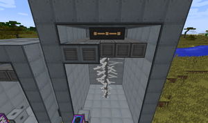
The Industrial Turbine multiblock structure is used to produce power from steam. Ideally, the steam is generated by a fission reactor directly, or by heating up water in the Thermoelectric Boiler with superheated sodium produced by a fission reactor.
Another integral use of the structure is to turn steam back into water when outfitted with Saturating Condensers, massively reducing the requirement on fresh water production by allowing you to reuse up to 100% of water.
Contents
Video Tutorials
https://www.youtube.com/watch?v=9EgZTwCnWwA&t - EsquilãoBR Tutorial PT-BR
https://www.youtube.com/watch?v=sZt5-_MF6Jw - Tutorial Made by MathewCell
https://www.youtube.com/watch?v=kHJSEUjCsyA - Tutorial Made by AidancBrady
Components
- Turbine Casing
- Turbine Vent
- Pressure Disperser
- Turbine Blades
- Turbine Rotor
- Rotational Complex
- Electromagnetic Coil
- Turbine Valve
- Structural Glass (Optional)
- Saturating Condenser (Optional)
Construction Notes
- Orientation can only be vertical.
- Length and Width (x,z) must be equal (the base must be a square).
- Maximum shaft height = min(2xLENGTH-5,14) [so blades don't touch sides]
- Maximum total height = min(2xLENGTH-1,18)
- Tank volume = LENGTH^2xROTOR_HEIGHT
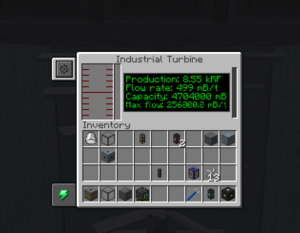
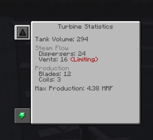
- Flow rate is determined by tank volume times dispersers (exact formula inside notes) or by vents - whichever is less. Each vent adds 32,000mB/t of flow rate, and each disperser can disperse 1,280mB/t of flow per block of interior volume.
- Energy production = FLOWxROTOR_HEIGHTx50RF/7
- 1 coil will support 4 blades. You'll never need more than 7 coils.
- Interior may ONLY be pressure dispersers, coils, shaft, blades, rotational complex, saturating condensers or air.
- Multiblock will sparkle redstone particles on final block placement, otherwise check your assembly.
- Minimal turbine size is 5x5 base with 5 blocks high.
- Maximum turbine size is 17x17 base with 18 blocks high.
Construction steps
- Build the base out of turbine casings and optional structural glass. (must be square) [the perimeter must be casings not glass]
- Place rotor shafts in the center, from the base to desired height.
- Add turbine blades to the rotor. (two for each rotor shaft)
- Place a rotational complex on top of the rotor.
- Completely fill the interior layer around the rotational complex with pressure dispersers.
- Place electromagnetic coils above the dispersers. They must touch the rotational complex and each other.
- Build the wireframe (the perimeters of the walls) out of turbine casings (you may have more empty layers above the coils to make room for more vents and condensers).
- Fill the walls, up to the height of the rotor, with turbine casings and/or structural glass and at least 2 turbine valves.
- Put in saturating condensers anywhere above the rotational complex, except in the walls or the ceiling.
- Fill the remaining walls and ceiling with turbine casings and/or turbine vents.
Water Cycle
By fitting the structure with saturating condensers, part of the steam will be refunded as water. This is highly helpful to maintain a net positive of water in a fission reactor system. Note that the water will be outputted from turbine vents instead of valves, and that the water is not accumulated: if nothing is connected, the condensed water simply disappears.
Flow Rate
- The "flow rate" is really an efficiency ratio: it measures how much of your turbine's maximum output you're actually getting. It can never be larger than 1.
- The actual maximum rate of steam flow (labeled MAX_RATE below) is limited by both the number of dispersers and the number of vents. Each vent can pass 32,000 mB/t; each disperser can disperse 1,280 mB/t *per block of interior volume*.
- "Interior volume" -- labeled `structure.lowerVolume` below -- means the inside volume of the rotor chamber. So if your base is 11x11 and you have 4 blocks of rotor shaft, then your interior volume is 9x9x4=324 blocks, and every disperser disperses 414,720 mB/t.
- The flow rate is the product of two numbers:
- The fill ratio of the turbine: (volume of steam)/(maximum volume of steam)
- The current rate of steam flow, as a fraction of MAX_RATE. Ideally this would just be 1, but you can't move more steam than is actually in your turbine -- so if (volume of steam) < MAX_RATE, you only get (volume of steam)/MAX_RATE.
- In addition, the actual energy gained per tick is capped by the energy storage of the turbine.
- As long as you have room to put the energy, the equation is just:
   GENERAL_DISPERSER_GAS_FLOW = 1280
   GENERAL_VENT_GAS_FLOW = 32000

   MAX_RATE = min(TURBINE_DISPERSER_COUNT * GENERAL_DISPERSER_GAS_FLOW * structure.lowerVolume, TURBINE_VENT_COUNT * GENERAL_VENT_GAS_FLOW)
   FLOW = min(1, TURBINE_STORED_AMOUNT / MAX_RATE) * (TURBINE_STORED_AMOUNT/TURBINE_MAX_STORED_AMOUNT) * MAX_RATE
Miscellaneous Notes
- Compatible with oredict steam from other mods such as TE/TF/RC/MFR/Big Reactors.
- The marking of "Limiting" on the vents stat simply means that it is not "optimal ratio". You can have fewer down to your desired steam flow rate.
- Turbine shuts down if internal battery fills with energy. It will restart automatically though you may also vent excess steam to prevent it from shutting down. As a turbine is often a critical part of any fission reactor water cycle, it is best to secure a large power bank such as an Induction Matrix for large scale operations.
Images
 |
 |
 |
| ||||||||||||||||||||||||||||||||||||||||||||||||||||||||||||||||||||||||||||||||||||||||||||||||||||||||||||||||||||||||||||||||||||||||||||


